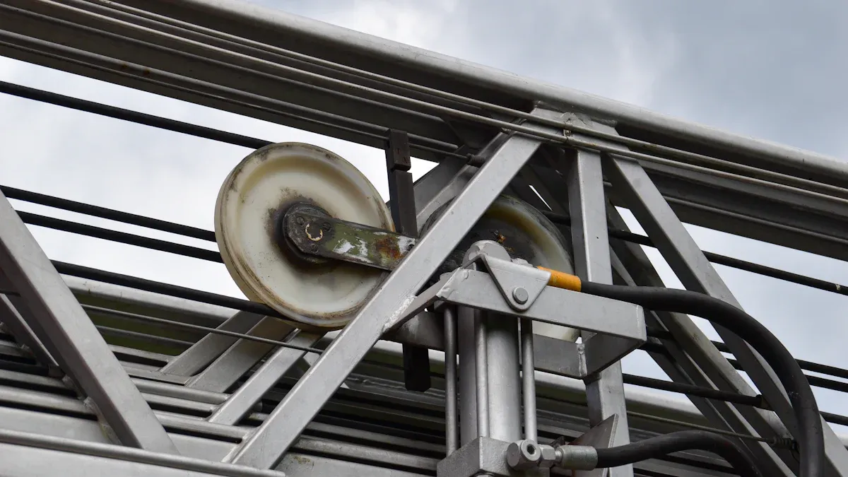
Custom hydraulic hoses are preferred for heavy equipment because pressure rating alone does not determine service suitability. Excavators, loaders, mining machines, cranes, and forestry equipment combine high pressure with repeated flexing, abrasion, heat, tight routing, and changing hose geometry. ISO 18752:2025 covers 10 pressure classes, 4 performance grades, 7 hose types, and nominal sizes from 5 to 102, showing how widely hydraulic requirements can vary. Parker also applies a 4:1 design factor to many hydraulic hose ratings. A properly specified custom assembly matches hose size, fittings, length, bend radius, fluid compatibility, temperature range, and external protection to the actual machine rather than forcing a stock hose into the installation.
A heavy-equipment hose works as part of an assembly, not as an isolated rubber tube. The finished assembly includes the inner tube, reinforcement, outer cover, couplings, sealing surfaces, and the route between two ports. Parker notes that assembly working pressure is limited by the lowest-rated component; in one published example, fittings rated at 12,000 psi do not raise a hose rated at 5,800 psi above 5,800 psi.
That difference explains why replacing a damaged hose by matching only diameter can produce a poor result. Two 3/4-inch hoses may share the same bore while differing in reinforcement, working pressure, outside diameter, bend radius, cover material, and allowable temperature. Gates lists one 3/4-inch two-wire-braid hose at 3,500 psi working pressure, 14,000 psi minimum burst pressure, and a 3.8-inch minimum bend radius.
A custom assembly should be specified from the pressure requirement outward: hose construction first, then bore, fittings, total length, orientation, temperature, fluid, bend allowance, and external protection. Changing one item can alter the acceptable choice for several others.
Pressure is also repetitive rather than constant. Every cylinder stroke and valve movement can change pressure, so reinforcement must tolerate repeated pressurization as well as the stated working pressure. A 4:1 design factor, for example, associates a 3,500 psi working-pressure hose with a 14,000 psi minimum burst figure in the Gates example; burst pressure remains a qualification figure, not an acceptable operating pressure.
A high pressure spiral hose becomes relevant when equipment requires pressure capability and construction beyond many conventional braided-hose applications. Spiral reinforcement commonly uses multiple wire layers arranged to manage high internal pressure with less wire movement than a simple crossed braid structure. The exact hose still has to be selected from its manufacturer's stated working pressure, size range, impulse performance, and fitting system.
The pressure requirement then affects routing. A hose that can contain 5,000 psi may still have a short service life if installation forces it below its stated bend radius. Gates specifically advises maintaining the specified minimum bend radius and recommends that bending should not begin closer than about 1.5 hose outside diameters from the end connection.
| Specification item | Example published data | Why custom sizing matters |
|---|---|---|
| Working pressure | 3,500 psi | Must meet the circuit requirement without using burst pressure as a working limit |
| Minimum burst pressure | 14,000 psi | Shows the 4:1 relationship in this hose example |
| Hose ID | 0.75 in / 19.1 mm | Affects fluid velocity and connection size |
| Minimum bend radius | 3.8 in / 96.5 mm | Determines how tightly the hose can be routed |
| Continuous temperature | -40°F to +212°F | Must cover both fluid and surrounding temperature |
| Outside diameter | 1.11 in / 28.2 mm | Affects clamp size, clearance, and bundle spacing |
Length must therefore be calculated with movement in mind rather than measured as the shortest distance between ports. Gates advises allowing for length change as a hose is pressurized, while Parker data for some hose families lists maximum length change at working pressure of about ±2%. On a 60-inch assembly, 2% equals 1.2 inches, enough to alter clearance around a bracket or moving joint.
An excavator boom shows the problem clearly. A line may look loose when the boom is folded but become nearly straight when the cylinder reaches another position. An assembly made 2 inches too short can pull against the coupling; one made substantially too long can form a loop that contacts steelwork during every cycle.
Fitting geometry reduces that problem before extra hose length is added. Straight, 45-degree, and 90-degree ends let the assembly leave a valve, pump, or cylinder in a more suitable direction. Gates routing guidance recommends suitable elbows or adapters where they relieve strain and improve access, rather than forcing the hose through a sharp bend immediately after the coupling.
Custom fabrication is particularly useful when two angled fittings must have a defined relationship. If a 90-degree fitting at one end must point 120 degrees relative to the fitting at the opposite end, the orientation can be set during assembly. Correct orientation avoids installing the hose with torsion, which Gates warns can contribute to hose failure or loosen connections under pressure.
External wear becomes the next concern once length and orientation are correct. Heavy equipment places hoses beside frames, boom structures, clamps, guards, attachments, and other lines. A pressure-capable hose can lose serviceability when rubbing removes the outer cover and begins exposing its steel reinforcement.
Gates specifically recommends routing hoses away from rubbing surfaces and using correctly sized clamps on longer runs. A clamp that is too large permits movement inside the clamp, increasing abrasion. On a machine operating 2,000 hours per year, even slight contact repeated through thousands of boom or steering movements gives the cover many opportunities to wear.
Custom assemblies can address that environment with an abrasion-resistant cover, textile sleeve, spiral guard, or localized protection where contact cannot be removed through routing. Protection should not be added without checking dimensions, because a guard increases outside diameter and can change clearance between neighboring lines.
Temperature deserves the same attention. ISO 18752:2025 lists oil-based hydraulic-fluid service ranges of -40°C to +100°C for AS, AC, BS, and BC hose types, and -40°C to +120°C for CS, CC, and DC types. The same standard gives water-based-fluid limits up to +70°C for the fluid groups identified in its scope.
Manufacturer products can differ further. Gates lists a high-temperature SAE 100R1 hose with continuous service from -40°F to +275°F and intermittent exposure to +300°F, while another two-wire hose is published for continuous operation only to +212°F. A hose should therefore be selected from its own data rather than from the temperature capability of another hose with the same bore.
Fluid type is part of the same specification. ISO 18752:2025 distinguishes oil-based HH, HL, HM, HR, and HV fluids from water-based HFC, HFAE, HFAS, and HFB fluids. Tube material that performs well with one fluid family should not automatically be assumed suitable for another, particularly when operating temperature is near the material's stated limit.
For a replacement assembly, the information supplied to the hose manufacturer should normally include:
-
Actual hose inside diameter and required working pressure, not only the thread size.
-
Port and fitting type at both ends, including sealing style and fitting angle.
-
Finished assembly length measured using the manufacturer's stated method.
-
Orientation between angled fittings, expressed in degrees where required.
-
Minimum available bend space and nearby surfaces that may contact the hose.
-
Hydraulic-fluid type and expected fluid temperature.
-
Ambient temperature near engines, exhaust components, or other hot areas.
-
Required abrasion sleeve, guard, fire-resistant cover, or other protection.
-
Equipment motion through the full articulation range, not only the parked position.
Recording those parameters also makes later maintenance more repeatable. A fleet with 25 similar loaders does not need technicians to reconstruct the same assembly from a damaged sample every time. A hose record can contain part number, ID, working pressure, length, fitting codes, fitting orientation, guard type, and machine position, allowing the same verified specification to be reproduced.
The choice between a stock hose and a custom hose can then be made from measurable conditions rather than price alone. A stock assembly is suitable when its length, pressure rating, connections, temperature range, bend radius, and routing all match the machine. Once adapters, excess loops, twisting, or reduced bend radius are needed to make it fit, the apparent saving becomes less convincing.
Component matching matters here because a stronger hose cannot compensate for a lower-rated coupling. Parker's published assembly example pairs 12,000 psi fittings with a 5,800 psi hose and limits the completed assembly to 5,800 psi. The lowest-rated part sets the assembly pressure rating, so hose and fittings should be treated as one engineered system.
Size selection also affects machine performance. A bore smaller than the equipment specification increases fluid velocity for the same flow rate and can increase pressure loss and heat generation. A much larger hose takes more space, requires larger fittings, may have a greater minimum bend radius, and can be harder to route through compact equipment structures.
Published product data illustrates the scale of the difference. Gates lists a 1-inch SAE 100R16 hose at 2,500 psi with a 4.5-inch minimum bend radius, while its 3/4-inch version can be rated at 3,500 psi with a 3.8-inch bend radius. Increasing diameter therefore does not automatically provide higher working pressure or easier routing.
Service conditions finally determine how much customization is useful. A protected return line inside a machine enclosure has different requirements from a boom-mounted pressure line exposed to mud, rock, weather, and constant movement. ISO 18752:2025 itself separates hydraulic hoses into 10 classes and 4 performance grades, rather than treating all reinforced hose as one interchangeable product group.
For heavy equipment working hundreds or thousands of hours each year, specifying the complete assembly gives maintenance teams measurable limits for pressure, temperature, bend radius, length, compatibility, and connection geometry. The result is a hose that fits the available space, moves with the equipment, uses the intended fittings, and operates within published manufacturer and industry limits.